Electrical Design Schematics (click on the schematics to see .pdf version)
We use microprocessor E128 board to control our robot.
E128 Pinouts and Target Commander
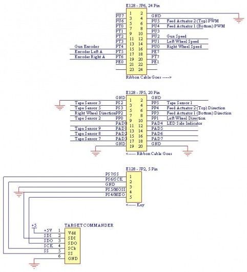
E128 is the brain of our robot. Here is the pinout from the E128 to other components of the robot such as PWM for drive wheel controller, PWM for the gun speed, and ammo (nerf ball) gate mechanism.
Adjustable Virtual Ground
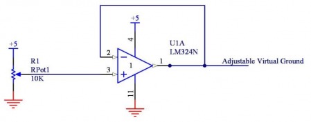
This circuit is really useful when incorporating with op-amp. We used it to test our tape sensors and many others.
LED Side Indicator
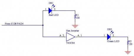
The name is self-explanatory. This circuit lets the spectators know which side that our robot is on. Note that this circuit uses only one output pin from E128. So one of the LEDs is always on.
Tape Sensor Module
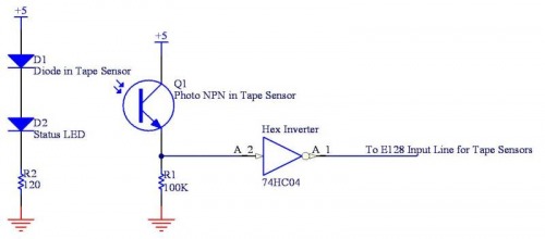
Tape sensor is one of our main field sensors for driving around the playing field. It allows our robot to reorient with the black I-shape and be ready to shoot the targets.
Drive Wheel Motor Circuit
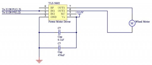
In order to get as much horsepower as possible from our beloved Maxon motor, we need a better and bigger H-bridge plus special drive circuit.
Ammo (Nerf ball) Feed Actuators
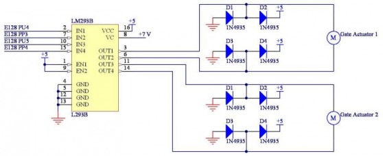
We use two door actuators as our ammo feeder. One for reloading the ball and another for releasing (or FIRE!!!) the ball.
Gun Speed Controller
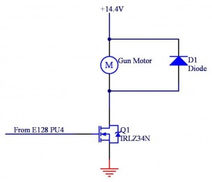
This circuit allows us to the drive the powerful gun motor without having to buy another special H-bridge drive circuit :)
Gun Encoder
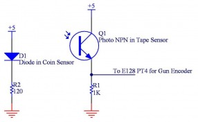
We utilize a coin sensor as our homemade encoder reader. Pretty cool and inexpensive.
Maxon Encoders
Since the Encoder uses open collectors, a pull-up resistor is required between the encoder output and +5.
