Design Calculations
Tape Sensors
For the IR LED side in the tape sensor, we also include a status LED for debugging purpose as well. We need to limit the current to approximately 17.5 mA with forward voltage of 1.7 V. The status LED has forward voltage of 1.2 V. Thus, the calculation is as follows:
V = IR
V-Vf,tape – Vf, status = IR
5 – 1.7 – 1.2 = (0.0175)R
R = 120 ohms
Thus, we selected R = 120 ohms.
V = IR
V-Vf,tape – Vf, status = IR
5 – 1.7 – 1.2 = (0.0175)R
R = 120 ohms
Thus, we selected R = 120 ohms.
Gun Motor
The IRLZ34 has ID = 30A, and VDSS = 55V. With a measured resistance of 3.4Ohms, at 14.4V, I=V/R = 14.4V/3.4 Ohms = 4.24A. We can not overheat the Z34, or the motor with our batteries.
Regulator
The regulator supplies current to 9 LEDs ( .015A per LED) and logic for the circuit. The current limit on the GL7805LS is 1A continuous, well above the amount of draw from all logic devices and LEDs combined.
Wheel Motors/Drivers
We first need to determine the resistance of the motor, Rm, with a multimeter. The motor resistance was found to be 11.3 Ohms. We implement a setup in which the H-bridge connects to ground through the motor and a resistor of known value.
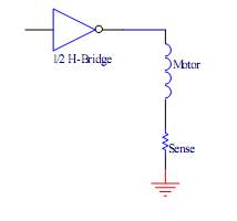
The voltage across the Sense resistor (1K Ohms) will be measured with the scope. Choose a low enough PWM frequency such that the rise of the voltage has ample time reach its final value. Measure the rise time of the voltage signal, , with the scope. Use the following formula to calculate the inductance of the motor, L.
L = T(Rs + Rm)
L was calculated to be 0.61 mH. Notice that the rise time we measured is not the rise time of the motor alone! The Sense resistance needs to be taken out of the equation. Calculate the rise time of the motor with the following formula.
Tmotor = L/Rm = 0.61mH/11.3Ohms = 54us
The PWM frequency was chosen to be greater than the inverse of the rise time.
f_drive = 1/Tmotor = 1/54us = 18.52 kHz.
However, this speed was far too fast for the LTE5206 H-bridges. Given a 10% duty cycle drive signal, what is the maximum PWM frequency that will
result in less that 2% difference between the drive signal high time and the voltage
applied to the motor? Use worst case specifications.
trise =20us switching + 30us delay =50us
Since we didn’t need especially precise PWM control (due to implementation of PID control) we reduced the PWM frequency to 440Hz, as a performance compromise.
Assuming a fresh 7.2V battery and a motor with a 1.71Ω armature resistance at stall,
how much power would you expect to be dissipated in the TLE-5206 (worst case)?
Rds(on) = .5Ohm*2 = 1Ohm
I = V/R = 7.2V/(1.7+1) = 2.66A
We need to verify that the LTE5206 can supply the current needed to drive the motor.
14.4V battery and a motor with a 1.71Ω armature resistance at stall,
Rds(on) = .5Ohm*2 = 1Ohm
I = V/R = 7.2V/(1.7+1) = 5.32A
For this reason, we limit our maximum duty cycle at stall to ~80%, easily below the threshold current of the drive chip.
Finally, the maximum repetitive reverse voltage for the 1N4935 Diode is 200V. Considering the placement of our other diodes, 200V is much greater than the maximum it will incur during operation. In addition, considering the good power dissipation characteristics of the 1N4935, it is highly improbable that the relatively small stall current for our operation will destroy the diode.
