Mechanical Design
Robot Chassis
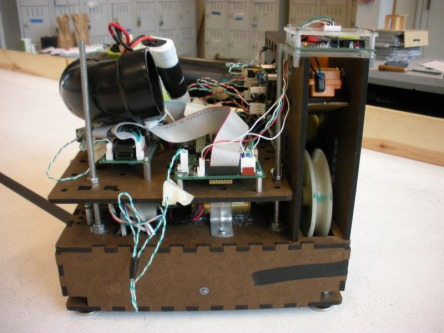
The frame of the robot is constructed from masonite and held together using box joints, slot joints, hot glue, and bolts. In hindsight, the bot should have been designed to be more accessible in case access is needed to the lower level components [which happened quite frequently]. The box shape allowed for maximum space and the platform structure provided easy placement of circuit boards and components. The gun and feeder mechanism where built directly into the structure of the robot. This allowed for simple construction and deconstruction, but was a little unforgiving in terms of shaft alignment for the pitching wheel. For stability, extra points of contact with the ground were added with sliders.
Drive Train
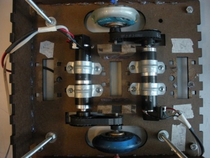
Two Maxon Motors were used to drive the robot. The motors were quite long. To fit inside the size specifications, belts were used to offset the motors allowing for a narrower wheel base. The timing pulleys used resulted in a 2.4:1 gear ratio allowing for larger output speeds than simply using the motors alone (which were quite slow, but powerful). Fortunately we did not need to use spider couplers; they only slop in the drive train was from the slack in the belts (which was negligible).
Pitching Machine Gun
Although there were easier to implement options, we decided to go for the Gold and minimize time by utilizing a pitching machine design to shoot the Nerf balls at the hat. Direct drive from a high speed motor was used to drive the pitching wheel. Our gun was amazingly accurate and precise, but we needed a way to adjust for the varying heights and distances of targets. After some thought, we decided that changing the angle of departure was too complicated and unnecessary. Simply controlling the speed of the pitching wheel would be sufficient. In the end, PI control for the pitching wheel was implemented with a homemade encoder wheel (24 ticks) in conjunction with a coin sensor.
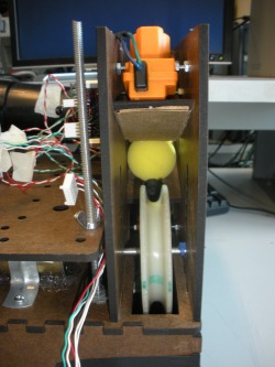 Pitching Machine Gun |
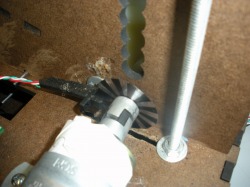 Homemade Encoder |
Ball Feeder Mechanism
The most time and thought of the design went into the ball feeder mechanism. Whatever method we chose had to be consistent and could not jam. The geometry of the feeder ramp and top plate was worked out so the ball would always catch when fed in - we never had any trouble with the ball not catching. The ball feeder mechanism employs two linear actuators (used in car door locks) spaced and sequenced OPEN/CLOSED appropriately for letting only one ball through at a time. If a ball did happen to not catch at the base of the wheel, we had the option to push it up into the wheel with the bottom actuator. The balls are held in a 2'' PVC pipe which is capable of holding approximately 16 balls, allowing for 2 balls per target.
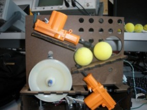 Ball Loaded |
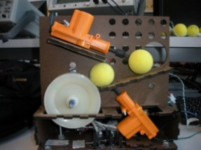 Ball Released |
Tape Sensor Layout
We had a total of 7 tape sensors on the bot - 3 in front, 3 in back, and 1 in the center. Although, we only used 4 - the three in front and the center. Looking back, having the two "straddling" tape sensors narrower would have helped our tape following abilities (we were a little too oscillatory). The center sensor was used when we were coming out from the base to find the tape. The middle sensor in front was used after we had found the tape and where rotating to align ourselves with the tape. Finally, the two front "straddling" sensors were used to guide ourselves along the tape and also use to indicate when we had reached the T.
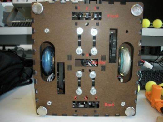
Tape Sensor Locations
